Description of the technical parameters of the turbine engine test bench
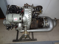
Description of the technical parameters of the turbine engine test benchTurbo-shaft engine GTD 350 designed to work in a team driving the helicopter, PZL Mi-2
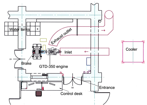
On the bench (Fig.1) is mounted turbo-shaft engine GTD 350 designed to work in a team driving the helicopter, PZL Mi-2, which consists of two these types of engines working in parallel. Power from the engine is transmitted to the rotor via a main gearbox shared for both units. The tail rotor is also driven by the main gearbox via the intermediate and the rear gear. The main gearbox is also a relay of power for all units helicopter.
Fig.1. Scheme of a test bench of the GTD-350 turbo-shaft engine
Laboratory space is divided into two main parts:
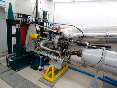
- engine test house (Fig.2)
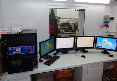
- pilot house (Fig.3)
In addition, the engine test bench includes:
- electrodynamic brake AMX 400/6000 (2000 Nm, 6000 rpm, 400 kW)
- brake cooling system with cooler CWT32 / 1200
- fuel tank of 600 dm3 (located in the yard)
- an air inlet,
- exhaust duct,
- engine oil cooling system,
- engine control system with the data acquisition system
Fig.2. Engine test house
Fig.3. Pilot house
In engine test bench situated on the ground we can obtain stationary characteristics of engine. However, on the basis of stationary characteristics we can also calculate characteristics referred to the aircraft engine fly conditions. In order to obtain a good engine performance during investigation conducted on the test bench, many parameters is determined, such as:
a) load torque or braking torque - MTN;
b) rotational speed of driving shaft - nTN;
c) power on the driving shaft (of power /free turbine) - PTN;
d) rotational speed of compressor- turbine shaft - nSP
e) inlet temperature of turbine - T3.
f) compression - π;
g) mass air flow rate - mpow
h) mass fuel flow rate – mp
i) thermal efficiency of engine – hc
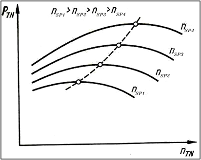
One of a more important performance of turbo-shaft engine, from the point of view of optimizing the operating point of engine, is so called power/driving turbine rotational characteristic, which shows the relationship of parameters such as: power, torque, specific fuel consumption and exhaust gas temperature as a function of power turbine rotational speed for constant rotational speed of compressor- turbine shaft (Fig.4).
In Fig. 4 we can see that there is an optimal speed power turbine for which at constant speed compressor-turbine (nSP = const) the maximum power turbine is obtained
Fig.4. Turbo-shaft engine speed performance of power PTN as a function of rotational speed
of power turbine nTN for different rotational speed of compressor-turbine nSP


